
While transferring the RF waves on a finite transmission line, for maximum power transfer from source to load (i.e. These are the impedance matching circuits. Transmission lines are the circuits that deliver power from a transmitter to an antenna and from an antenna to a receiver. Calculation of the length of a short circuited piece of transmission line to provide a required capacitive or inductive reactance.īefore plotting on a Smith Chart we need to study a few terms such as transmission line, characteristic impedance, standing wave, etc.

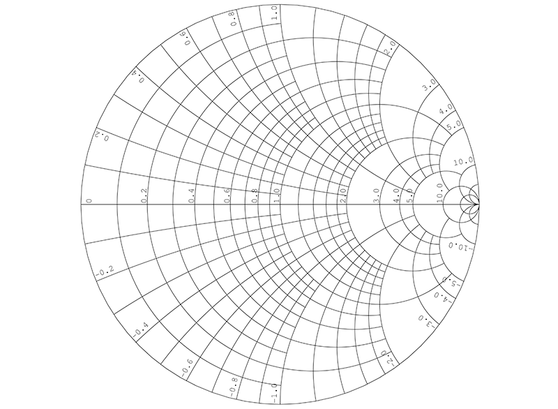
Impedance calculations on any transmission line, on any load.Admittance calculations on any transmission line, on any load.The important applications of a Smith Chart are as follows: The complete circle of the Smith Chart represents a half wavelength along the straight line. The horizontal axis represents the normalized resistance and the normalized line reactance is shown on the outer edge of the circles. The figure to the right shows the Smith Chart. One is the set of complete circles whose centers lie on the straight line and the other one is the set of two arc circles which lie on the either sides of the straight line. It consists of two sets of circles for plotting various parameters of mismatched transmission lines. The Smith Chart is the most used tool for microwave engineers to visualize complex-valued quantities and calculate the mapping between them. It is the circular plot of the characteristics of microwave components. Furthermore, the SMITH CHART provides the ideal medium for visualization of the principle of operation of such transformers and for quantitatively determining their specific design constants.The Smith Chart is the graphical representation of a complex mathematical equation. These devices are described in some detail herein since it is through its terminations alone that the transmission characteristics of waves along any given waveguide can be controlled.
#Smith chart component calculator series#
Slug transformers, on the other hand, are sections of line of appropriate characteristic impedance (or characteristic admittance) and length connected in series with, and forming a continuation of, the main line. Matching stubs or building-out sections, as they are sometimes called, are sections of transmission line, frequently of the same characteristic impedance (or characteristic admittance) as that of the main line, and either open or short-circuited at their far end, connected in shunt with the main line at any one of several permissible positions in the general location where it is desired to provide the match. These include the single and the dual matching stub, and the single and the dual matching slug transformers. Several commonly used devices for obtaining a match at the load end of a transmission line will be described in this chapter. Waveguide Impedance and Admittance Matching
#Smith chart component calculator software#
This edition includes a new chapter with example designs and description of the winSMITH software accessory. The text provides tutorial material on transmission line theory and behavior, circuit representation on the chart, matching networks, network transformations and broadband matching. This classic reference book describes how the chart is used for designing lumped element and transmission line circuits. It covers the history, development and applications of the Smith Chart. Smith, the originator of the Smith Chart. This is the second edition of Electronic Applications of the Smith Chart, written by Phillip H.


 0 kommentar(er)
